Build-A-VAWT
Finally! The ultimate stackable, modular, open-source, customizable, green energy community project for all the VAWT enthusiasts out there! VAWTs are gaining increasing attention for their low profile and sleek appearance. This type specifically is much easier to make than a HAWT, and I think it's a good intro for someone that has never played around with generating their own power before. Even if one chooses not to, though, it still looks great on a balcony.
As I mentioned, the real excitement in Build-a-VAWT comes from the fact that it's modular and uses a standardized mount, so I really hope it takes off and others design fun parts as well. This post will mostly detail the geometries needed to comply with the BAV mounting system. For information on best practices in printing and assembling your own BAV, you can watch my YouTube video below.
My BAV shafts have an exterior diameter of 30mm and a variable interior diameter that must be no less than 8mm (the ID of the 608 bearings). Generally, I keep my interior diameter at 19.20mm to save plastic while being strong, and I open it up to 22.20mm when a bearing is inserted.
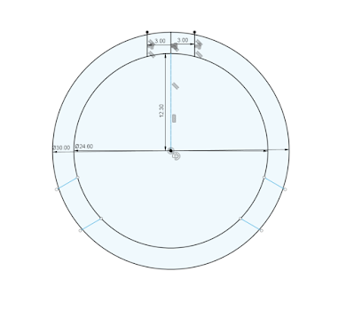
This is the mounting schematic for the female joint. Note that all figures are minimum values and are quoted in mm.The female joint is created by drawing two circles of dimeters 24.60 and 30mm with the same midpoint. Then, a section is cut by drawing parallel lines such that they are 6mm apart. The lines must intersect both circles and must be perpendicular to a ray that intersects the midpoint. A circular pattern is then performed at the midpoint, creating three segments that are then cut at least 5mm deep from the body. Additional dimensions are shown below.
Orientation-wise, the windmill should be oriented such that male parts face down, while parts are typically printed males-up to minimize supports. Female mounting holes are small enough to be printed with no supports, and should be.
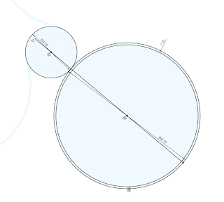
To create the profile for the wings, a 30mm circle is drawn. Then, an 85mm circle is drawn with one single tangential point between the two. The 85mm circle is then offset by 1.2mm to create a circle with a diameter of 82.6mm, sharing a centerpoint with the 85mm circle. A line is then drawn from the center of the small circle, through the tangential point, through the centerpoint of the 85mm circle, and to the far edge of the 85mm circle. This creates a C-shape that can be extruded.
Note that the line that is drawn at the end of the last paragraph must bisect one of the three mounting guides. This must be true for both the male and female mounting guides. If the part has a 15 degree twist, the mounting holes should be 15 degrees offset. This is imperative to ensure all BaV parts keep the same lines.
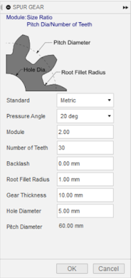
I've also designed several gears. We're going to use a really simple gear standard for Build-a-VAWT: modulus 2, root fillet radius 1. Gears should still have male and female mounts, as well as bearing mounts if reasonably possible. If possible, inserts should be used to allow gears to be used as either a drive gear or a driven gear. This will reduce waste and encourage re-use of parts.
Thanks for contributing to Build-a-VAWT components! A few closing reminders:
- Male mounts face down
- Turbines should be mounted such that curvy parts form a shrowd, not a channel. I've found they spin better this way (for some reason) and more importantly, throw water off and away from the turbine in rain.
- 608 bearings should be lubricated prior to use. This is a very low-load application, so WD-40 will be just fine
- Any part that can have a spot for a bearing mount should have one.
- Parts that might not necessarily need a bearing mount are parts that are <7mm tall or cannot have an ID of <22mm.


Neat design. No mention of a motor or sizing for a motor?
ReplyDeleteNo motor mounts have been created yet, but the first mounts will be made to fit NEMA-17 steppers, the same ones that are prominent in 3D printers: https://amzn.to/3K3WAd4
DeleteThanks for this as well as the video. Do you have a motor/generator that yours is hooked up to?
ReplyDeleteNo motor mounts have been created yet, but the first mounts will be made to fit NEMA-17 steppers, the same ones that are prominent in 3D printers: https://amzn.to/3K3WAd4
Deletecurrently building one and looking at possible off grid applications. ive triied building a motor mount for it but currently failing.. any ETA on a motor mount file for the nema 17 motors.
ReplyDeleteWould you consider publishing your F360 files or .step files? It would save some time not having to conver from stl, etc.
ReplyDeleteI just ordered hardware and downloaded the files, I will be printing and assembling in the next few weeks to see how much power I can generate.
ReplyDeleteGreat project, any news on compatible generators yet
ReplyDeleteHey Christopher just watched your video about BuildAVats on YouTube. Have you created a motor for your design yet? I'd love to build some functional vertical wind turbines for my house and I love your modular concept. Unfortunately building my own motor is a bit out of my wheelhouse and YouTubers always seem to glaze over the part where they modify their motors in their instructional videos.
ReplyDelete